Log In
Training
Tutorial
Article
Introduction to Safety-Related Features - Part 1. Safety-Rated Stop, Monitoring, and I/O
Basic
60 min
In this course, you will learn about Doosan robot’s safety-related features regarding safety-rated stop, monitoring, and I/O.
1. Getting Started
A collaborative robot is a robot that can be used without a fence in the same space as a worker. Therefore, features related to the safety of workers, robots, and work spaces are very important.
Doosan robot provides the industry’s highest collision sensitivity with torque sensors on all six joints. Traits like this are specifically incorporated into various safety-related features, including collision detection, for robot use with human workers.
Doosan robot uses a variety of safety-rated monitoring features and electrical interfaces to protect the user and itself, and can also be connected to other equipment and additional safety devices. The performance of each safety-rated monitoring feature and interface meets not only Category 3 and Performance Level d (PL d) described in ISO 13849-1 but also Hardware Fault Tolerance 1 and Safety Integrity Level 2(SIL 2) described in IEC 62061. Safety certifications such as NRTL (U.S.), CE (Europe) and KCs (Korea) have also been attained.
This course will introduce Doosan robot’s safety-related features such as safety-rated stop and monitoring function, and I/O.
※ Precautions for safety-related features
- Set up a workcell using the robot’s safety-related functions and interfaces according to the risk assessment performed by the system integrator in regard to the robot’s application. For the information necessary for this process, please sufficiently acquaint yourself with Doosan Robotics Installation and User manual and consult it.
- When the robot’s safety system has found a system fault (when a wire breakage has occurred in the emergency stop circuit), when the position sensor has been damaged, or when a hardware abnormality such as a failure with control-purpose communication has been detected: stop category 0 starts immediately. When the robot’s safety system detects a violation during the execution of safety monitoring (when the emergency stop switch has been pressed), when a protective stop signal has been inputted, when an external shock has been detected, or when a physical parameter such as the robot’s position, speed, or momentum has exceeded its set limit: the robot is stopped according to the stop mode specified in the Safety settings menu. (Select one from among stop categories 0, 1 and 2)
2. Safety-Rated Stop Function
The safety-rated stop function and stop monitoring function of Doosan Robotics use the safety function defined in IEC 61800-5-2.
The stop functions provided for user’s safety are as follows.
- STO(Safe Torque Off): All Stop Modes corresponding to Stop Category 0 immediately cut off the power supply to all joint module motors, and brake engagement forces the operation to stop. The brake for each joint of the robot is not intended for deceleration, but for keeping the robot in stop status when its operating power has been lost due to reasons such as a power cut-off. Frequent use of STO can wear the brake and shorten the life span of the decelerator. Therefore, we recommend you use SS1 instead, unless the use of STO is absolutely necessary.
- SS1(Safe Stop 1): All joints are stopped with maximum deceleration by a Stop Mode corresponding to Stop Category 1, the power supply to the motor is cut off, and the brake is engaged to stop. As the operation of STO mode, the robot is decelerated and stopped. Also the motor is in the state of power down. Operation of the robot is practicable under the condition Servo On after releasing stop function.
- SS2(Safe Stop 2): All joints are stopped with maximum deceleration by a Stop Mode corresponding to Stop Category 2, and SOS (Safe Operating Stop) is engaged.
The stop monitoring functions used together are as follows.
- SOS(Safe Operating Stop): In this mode, the robot’s current position is maintained in the Servo On status, in which the motor power is supplied, and the brake has not been engaged. Once an abnormal position change is detected in this mode, the robot switches to STO.
The user can selectively apply the Safety-Rated Stop function for the following conditions in the Safe Stop Mode in the Safety tab of the Setting menu. Please refer to the installation manual for more detailed function definition and stop mode specifications.
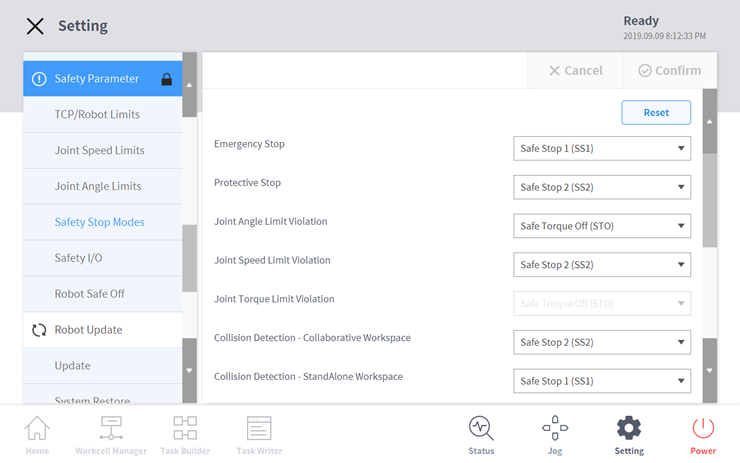
The following describes the two representative stop modes supported by Doosan robot.
2.1 Emergency Stop: The emergency stop function is activated if the Emergency Stop switch of TP is pressed or if the Emergency Stop switch connected to the TBSFT EM terminal is pressed.

※ Precautions for Emergency Stop
- For emergency stop, SS1(Safe Stop 1) Mode is set as a default.
- If an additional emergency stop button is required, you can attach one to the control box after performing a risk assessment.
- Emergency stop must not be used as a means of reducing risk and must be used as a secondary protective measure.
- If an additional emergency stop button needs to be connected to the control box, you must determine whether to do so through a robot application risk assessment. Additional emergency stop buttons must comply with I EC 60947 5 5.
[Try it]
Change the emergency stop category to STO and SS1 respectively in the Setting – Safety – Safe Stop Mode menu and check the difference between the two modes by pressing the emergency stop button during robot operation.
2.2 Protective Stop: The protective stop function is activated if the protective device connected to the TBSFT PR terminal is activated.
3. Safety-Rated Monitoring Function
Doosan robots feature a safety rated monitoring function that can be used as a risk reduction measure through risk assessment.
The monitoring function can be applied to the following categories. Please refer to the installation manual for more detailed function definition and stop mode specifications.
- Joint Position Monitoring (SLP): Limits the maximum rotation angle of a joint
- Joint Speed Monitoring (SLS): Limits the maximum rotation speed of a joint
- TCP Position/Direction Monitoring: Limits and monitors TCP position/direction at an orthogonal space (Operating area, independent work area, collaboration work area, restricted area, tool direction retainment monitoring area, collision detection specification area)
- TCP Speed Monitoring: Limits the maximum TCP movement speed
- TCP External Force Monitoring: Limits the external force applied to TCP
- Collision Detection: Limits the torque of external force applied to the robot arm and each joint
- Momentum Monitoring: Limits the maximum momentum applied to the robot arm
- Mechanical Power Monitoring: Limits the maximum power the robot arm can output
The threshold for each monitoring function can be configured at Setting – Safety Parameter of the TP UI. The following is an example of setting the threshold for joint position monitoring.
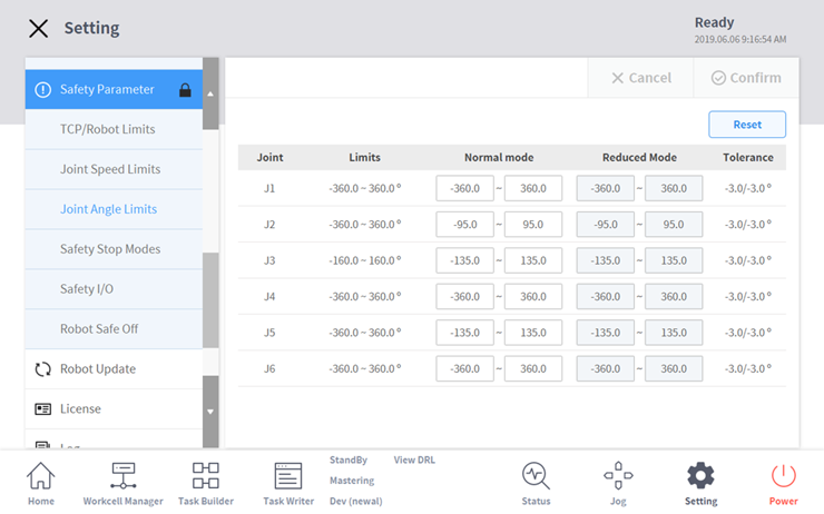
The stop condition of the robot according to the monitoring function can be set in the Safe Stop Mode menu introduced previously.
[Try it]
In the Setting – Safety – Tool Center Point/Robot Threshold menu, change the normal mode value of collision detection to 50 and 90, and check the difference in sensitivity of collision detection during robot operation.
※ Safety threshold is the condition where the safety rating monitoring function begins to stop. When stopping is complete, the position and force applied externally may be different from the configured safety threshold.
4. Safety-Rated IO
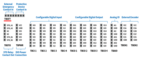
The robots of Doosan Robotics feature a safety-rated input interface capable of connecting protective stop signals from safety protective devices, external emergency stop signal input and 3 position Enable Switch.
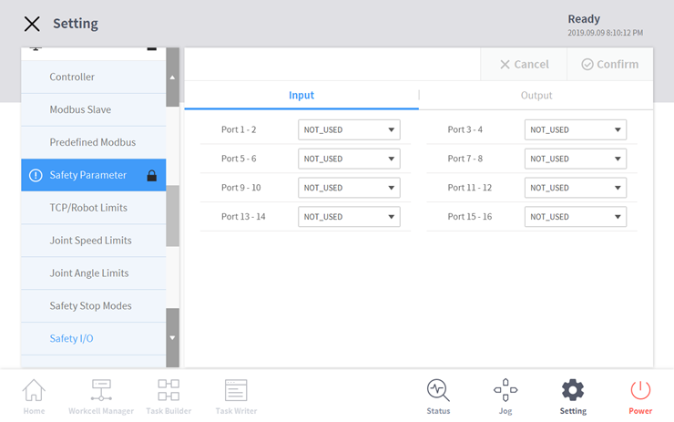
Safety-rated input/output can be configured in the Safety tab of the Setting menu.
For example, according to the external emergency stop signal, the robot’s SS2 stop function can be used or the robot’s operational status can be communicated to an external device.
- If a discrepancy between input signals is detected based on a redundant interface, or a discrepancy is detected in the feedback on the output signal, the robot is stopped and an error message is displayed. A function defined in combination such as ports 1-2 and 3-4 means a redundant interface is being used.
For each port combination, the following conditions can be set.
[Safety Input settings]
- Safe Torque Off: When low, immediately cuts off the motor power and force stops the robot by engaging the brake.
- Emergency Stop: When low, stops the robot according to the stop mode for emergency stop set in safety stop mode.
- Protective Stop: When low, stops the robot according to the stop mode for protective stop set in safety stop mode.
- Reduced Speed: When low, if the collaborative workspace has not been set, the robot operates at 20% of the speed set in Task. If there is an operation speed ratio specified upon the setting up of the collaborative workspace, the robot operates at a decreased speed corresponding to that ratio.
- 3 Pos Enable Switch: An operation permission device for operator protection used when connecting the 3-position switch. When low, disables the jog feature in manual mode, Servo On unavailable.
- Handguiding Switch: An operation permission device for operator protection used when connecting the handguiding switch. When low, Handguiding unavailable.
- Playback Resume: After using manual guide including handguiding during Auto mode, used to resume the execution of the program. When high, resumes the execution of the Auto mode program.
- Protective Stop & Auto Resume: Used with safety device (ex. safety mat etc.) and when high, in case of ‘protective stop’ by input signal, Program restart is operated automatically, without the manual execution of ‘program restart’ using the Teach Pendant.
- Dynamic Zone Enable: Used when collision temporary space is activated dynamically and when high, under the registration of safety input for collision temporary space, collision temporary space is activated.
[Safety Output settings]
- Emergency Stop: Used to notify the external system of the necessity of emergency stop upon the detection of the pressing of the TP emergency stop switch or an external emergency stop switch, or the detection of an error by self-diagnosis. When low, emergency stop is required.
- Safe Torque Off: When low, the robot is in STO status.
- Safe Operating Stop: When low, the robot is in SOS status.
- Safe Stop Event: When low, a safety stop situation occurs.
- Normal Speed: When low, the robot operates at the normal speed set in Task.
- Reduced Speed: When low, the robot is located in the collaborative workspace or operates at a decreased speed due to the input of an external deceleration mode signal.
- Auto Mode: When low, the current status of the robot is in Auto mode.
- Manual Mode: When low, the current status of the robot is in Manual mode.
- Standalone Workspace: When low, the robot’s TCP is located in the standalone workspace.
- Collaborative Workspace: When low, the robot’s TCP is located in the collaborative workspace.
- Collision Detection Overriding Zone: When low, the robot’s TCP is located in the separately designated collision detection area.
- Tool Orientation Monitoring Zone: When low, the robot’s TCP is located in the tool direction retainment monitoring area.
[Try it]
Prepare an external emergency stop button, connect it to port 1-2, and check the emergency stop mode occur during robot operation. When using an external emergency stop button for emergency stop mode, high is the normal condition and low is the emergency stop condition.
5. Summary
This course introduced safety-related features provided by Doosan robot. According to the safety-rated stop and monitoring functions, various stop modes can be configured. When safety input/output signals are connected with external systems, the robot’s status can be modified or monitored. Please refer to the Installation or User manual for more detailed information.
Recommended resources
- International Organization for Standardization, ISO 10218-1 & 2
- International Organization for Standardization Technical Specification, ISO/TS 15066
- Doosan Robotics Installation & User manual, https://robotlab.doosanrobotics.com
※ Doosan Robotics has copyright and intellectual property rights to all content and all designs shown in this material. Therefore, any use, copying, or dissemination of them without written permission from Doosan Robotics is prohibited. Please note that you will be held solely responsible for any improper use or alteration of the patent rights of Doosan Robotics.
Recommended Training Class
These learning opportunities can help you get started quickly.
Article
Programming with the robot’s PROFINET IO Device Function
Article
How to program with EtherNet/IP
Article
How to program using TCP/IP Socket