Log In
Training
Tutorial
Article
How to program with EtherNet/IP
Core
60 min
In this course you will learn how to program with EtherNet/IP
1. Getting Started
EtherNet/IP is one of the Industrial Ethernet protocols developed by the Open DeviceNet Vendors Association (ODVA) and ControlNet International (CI), which is used to accurately exchange data between industrial equipment.
Doosan Robot provides EtherNet/IP Device function (Robot information monitoring, General Purpose Register) with software without separate HW device.
- Support: SW version M2.3.1 or later
In this course, we will learn how to program using EtherNet/IP provided by Doosan Robotics.
2. Preparations
This course is shows how to connect Doosan Robot and PLC of Rockwell Automation, a representative EtherNet/IP device.
Preparations
- Rock well automation PLC (Ex. Allen-Bradley Compact Logix 1769-L30ER) & PC with Studio 5000 installed.
- Doosan Robotics M1013
- Setting file: DoosanRobot.eds, DoosanRobot_EIP.L5X, IO Table_eip.pdf (Can be downloaded from Robot LAB)
During a booting process of the Doosan Robots, the EtherNet/IP Device function is automatically executed during the controller booting. Therefore, there is no additional setting for the robot or teach pendant.
- The robot network can be set with general TCP/IP communication and nothing to do with EtherNet/IP communication.
The connection between PLC, robot and computer for EtherNet/IP communication is as follows.
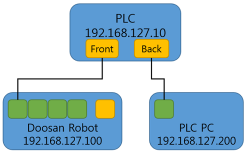
※ Please find an actual IP address of a robot by checking the ‘teach pendant’ prior to this network set up.
3. Connecting Doosan Robots with PLC
3.1 PLC and PLC PC (Setup PC) communication environment set up
Configure your PLC PC (PC for Setup) with ‘RSLinx Classic Lite’ from Allen Brandley. Before setting the environment for communication, be sure to complete the following settings after completing the IP settings of the PLC PC. If the network bands are different, scanning will not be possible.
3.2 Configure Drives setting
To use EtherNet/IP on the PLC PC, proceed as follows to enable EtherNet/IP communication on the Ethernet port of the PLC PC.
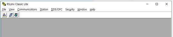
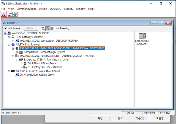
- Run RSLinx Classic Lite and from the top menus, click on ‘Configure Drives’ from ‘Communications’ menu.
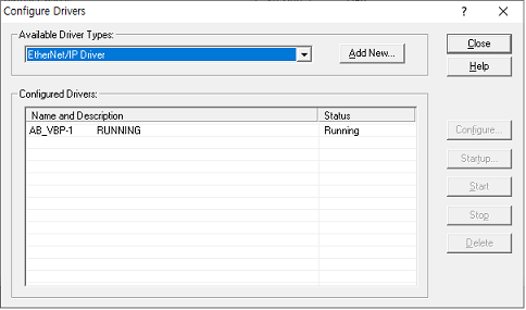
- Click ‘Add New’ after selecting ‘EtherNet/IP Driver’ from the ‘Available Driver Types’.
- Check and select ‘Ethernet Port’ that you want to use.
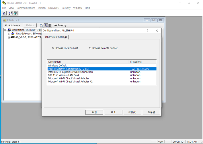
- Begin PLC search by clicking the icon inside the red box.
※ Sometimes, AB PLC is shipped without the firmware. In this case, it is recommended to download the firmware by connecting USB cable with Studio5000.
4. PLC project configuration
Use Allen Brandley's Studio5000 to build programs and environments that need to be run on a real PLC.
4.1 Creating a project
- Run ‘Windows’ → Rockwell Software → Studio5000, click ‘New Project’.
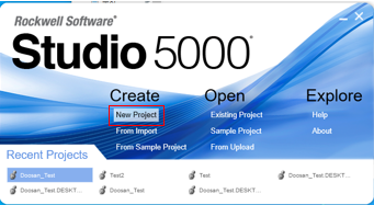
- After selecting ‘New Project’, the window for selecting the AB PLC to be used will be displayed as shown below. Select the PLC model and fill in the project name and click ‘Finish’.
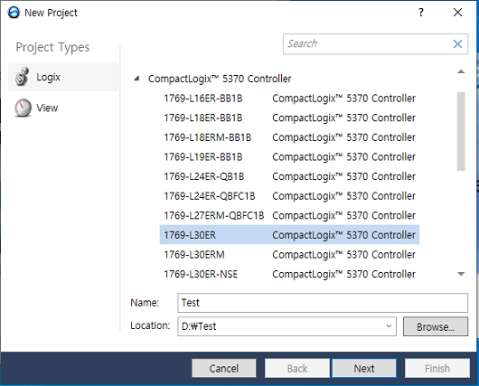
※ If you don't know the detailed model name of the PLC, please refer to the detailed model name from the PLC search from the previous step.
4.2 Adding EDS Files
Please follow below procedures to load saved file of detailed information on Adapter (Slave) into the PLC project. Please prepare the latest EDS file from Doosan Robotics homepage prior to following steps.
- TOOLS → select ‘EDS Hardware Installation Tool’
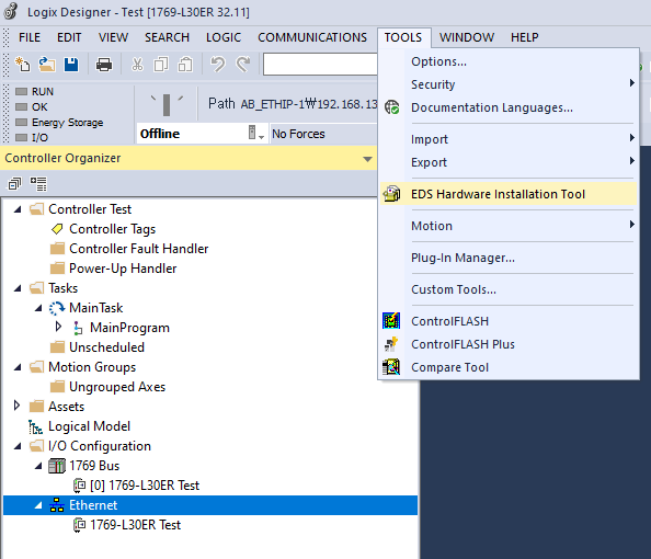
- Click ‘Register an EDS file’ → Select ‘Register a single file’ → Select ‘Browse’, Add latest ‘eds’ file.
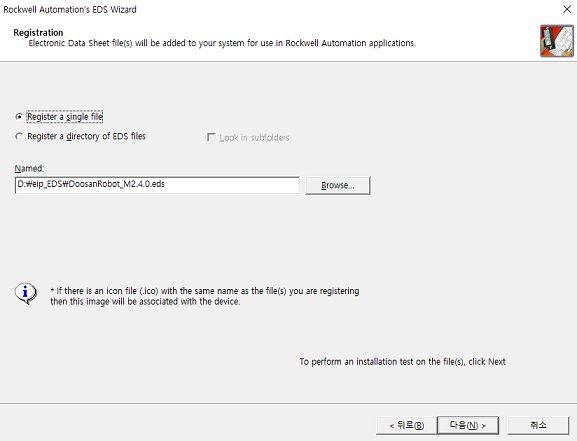
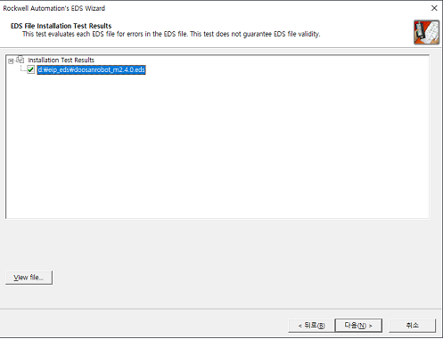
- Click ‘Next’
- Select ‘Change Icon’, chose file with Doosan Robot Logo image from the ‘EDS File (zip file)’
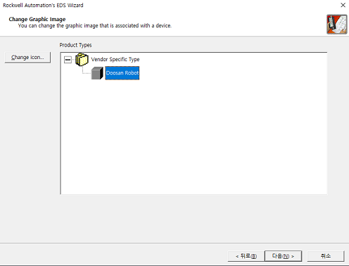
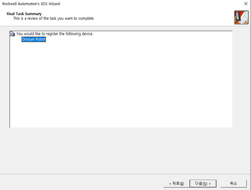
- Click ‘Finish’.
4.3 EtherNet/IP Device adding (adding robot)
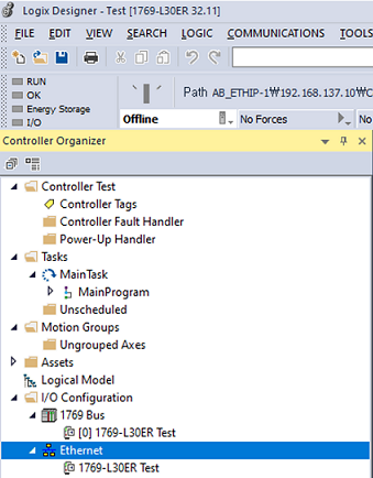
Add a device (Doosan Robot) of Slave of EtherNet/IP to be used in the project. On the left side of the main screen, expand the I/O Configuration of the ‘Controller Organizer’ and there is an Ethernet item. Right-click and choose ‘Add Module’.
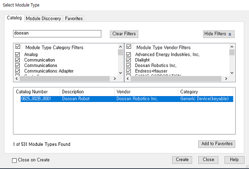
- Search ‘Doosan’ from the window of ‘Select Module Type’, select ‘Create’ and move on to robot detailed setting.
- Enter the name and the IP address of the robot from ‘general’ items. Select ‘OK’ and ‘Close’.
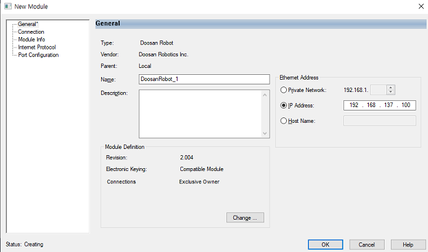
※ Find the use the actual IP address of the robot from the T/P.
4.4 Adding UDT File
Doosan Robot runs as a slave of Ethernet/IP and provides various information to the numerical control panel (PLC). By using UDT file, lots of work can be reduced Instead of defining every information provided from robot. Please refer to Doosan Robotics webpage for the latest UDT file.
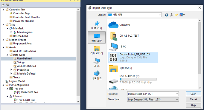
- If you expand the controller organizer assets on the left side of the main page, you will find the ‘Data Types’ item. Select ‘User-Defined’, right click and select ‘Add Module’.
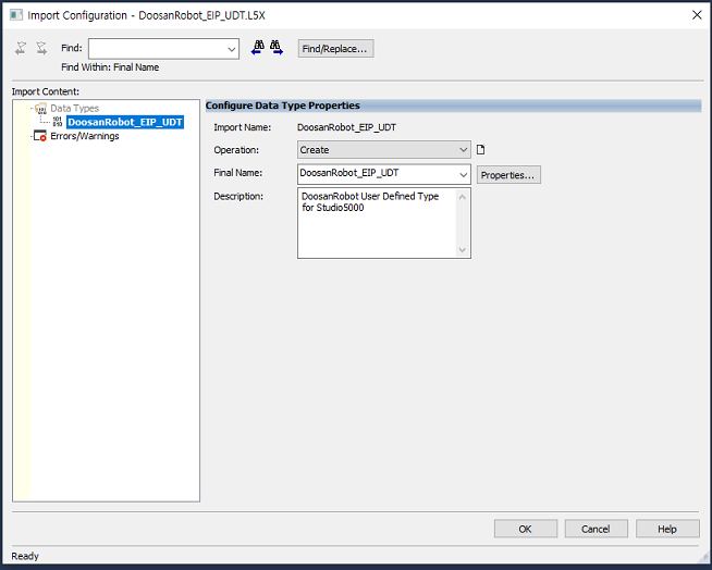
- Select the latest UDT file (.L5X) from the ‘Import Data Type’ window.
- If UDT file is selected properly, the following screen will be displayed then click ‘OK’.
4.5 Tag addition for the data monitoring
In order to make use of the data sent from the robot, the data should be saved in the user defined data area added in advance. In case of AB PLC, data received through EtherNet/IP is basically only received in the form of SINT (1 byte). In order to use such data on PLC, data must be formatted according to I/O message format.
- In this step, set the space for data to be saved.
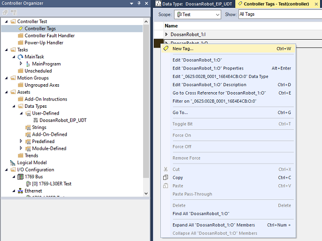
- If you expand the controller of ‘Controller Organizer’ on the left side of the main page, there is a ‘Controller Tags’ item. Double click on it and a screen like the one on the right will appear. Right click and click ‘New Tag’ to create new tags.
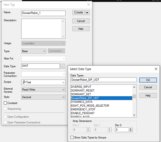
- Enter the Tag name in front of the ‘Name’.
- Select previously added ‘User Defined’(DoosanRobot_EIP_UDT) and create it.
4.6 Copy data from Ethernet/IP Slave into ‘User Defined Tag’.
- In order to copy the appropriate data to the ‘User Defined Tag’, the received Ethernet/IP data is basically copied to the Tag by using the ‘COP’ or ‘CPS’ command.
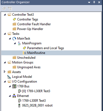
- Expand ‘Controller Organizer Tasks’ on the left side of the main page and select ‘MainRoutine’.
- Click on ‘CPS’ command after selecting ‘File Misc’ from PLC commands.
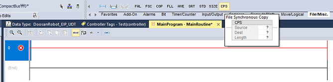
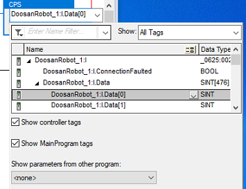
- Following window will be displayed with selection of ‘?’ from the source among CPS command Blocks. This is the window to select the source of data and there is a tag ': I' after the name of the robot. Expand that data tag to select the first item from the list.
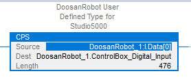
- For the ‘Dest’ items, if you expand all the way after selecting a ‘Tag’ added through ‘User Defined’, ‘ControlBox_Digital_Input’ item is initially selected. Confirm the selection.
- For the ‘Length’ enter ‘476’, because the total size of the data(T(Robot) → O(PLC)) that PLC has to receive on a I/O Message Format is 476 byte.
5. PLC Project download and running
Download the PLC configuration and program set with ‘Studio5000’ into PLC and run it. Communication environment setting between PLC and PLC PC need to be completed in order to properly download and run the program. Prior to start this procedure, you must change the PLC mode to ‘Remote Mode’. There is a switch that can be manipulated with a key type or a three-stage switch type on the PLC body.
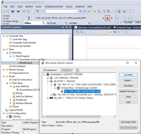
5.1 Project Download
- Click on the icon below from the menu of Studio5000. ‘Who Active’ window will be displayed and select target PLC for the download by expanding windows of ’AB_ETHIP-x, Ethernet’.
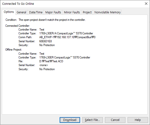
- If Go Online is selected and connected properly, the following window will be displayed. If the program built in the present PLC PC and the program stored in the present PLC are different, a window will be displayed for automatic download. Click ‘Download’ to download the PLC project to the PLC.
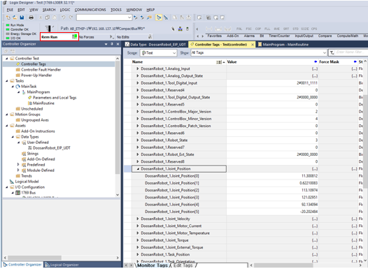
- In the picture below, click ‘Run Mode’ to run the program in PLC. Click ‘Controller Tags’ and select the ‘User Defined Tags’ to check various information from the Robot.
6. Using GPR on a Robot
In the task programming environment (Task Builder, Task Writer), you can use the DRL commands below to read or modify the values of the set registers.
- set_output_register_int(address, val)
- set_output_register_float(address, val)
- get_output_register_bit(address)
- get_output_register_int(address)
- get_output_register_float(address)
- get_input_register_bit(address)
- get_input_register_int(address)
- get_input_register_float(address)
These commands can be used in ‘If’ conditional statements or custom code commands.
7. Conclusion
In this lesson, you learned how to set up and program the EtherNet/IP. Please refer to the Software Manual of Studio 5000 on the Rockwell homepage and the Programming Manual for more detailed instructions
References
- Rockwell literature library, https://www.rockwellautomation.com/en_NA/literature-library/overview.page
- Doosan Robotics Programming Manual, https://robotlab.doosanrobotics.com
※ Doosan Robotics has copyright and intellectual property rights to all content and all designs shown in this material. Therefore, any use, copying, or dissemination of them without written permission from Doosan Robotics is prohibited. Please note that you will be held solely responsible for any improper use or alteration of the patent rights of Doosan Robotics.
Recommended Training Class
These learning opportunities can help you get started quickly.
Article
Programming with the robot’s PROFINET IO Device Function
Article
How to program using TCP/IP Socket
Article
How to program using Modbus-TCP