Log In
Training
Tutorial
Article
How to install and get started with Doosan robot
Basic
30 min
In this course, you will learn about how to install and get started with Doosan robot.
1. Getting started
In this course, you will learn about how to install a Doosan robot and get it started.
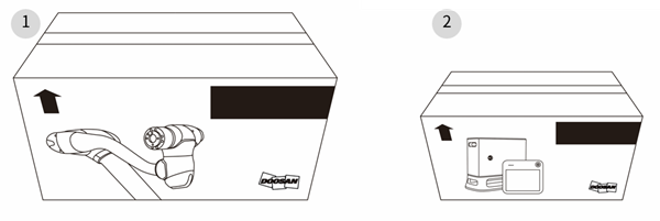
When you purchase a Doosan robot, the robot system will be delivered in two boxes. The first big box contains the robot arm, and the second small box contains the controller and teach pendant. To ensure safe delivery, all products are enclosed in protective materials, so please remove them with caution.
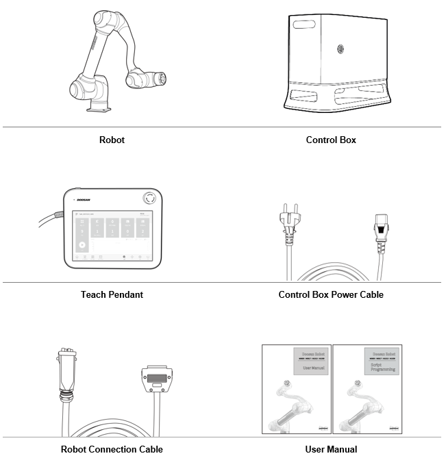
2. Components of Doosan Robot
All six components that are essential when using the Doosan robot are contained in the two boxes delivered. Please refer to the installation manual for detailed specifications on each component.
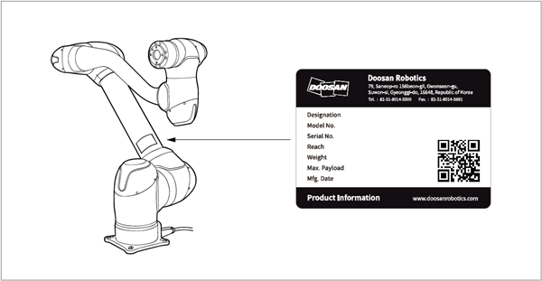
The labels to check the information of the robot arm and controller can be found in the following locations:
- Be careful not to remove or damage the labels attached to the robot and controller.

※ The following additional parts are required to fix the base of the robot arm and to mount a tool on the tool flange.
- For the base: Four M8 bolts, two positioning pin of Φ5
- For the tool flange: Four M6 bolts, one positioning pin of Φ6
3. Installation of the Robot
The following procedures are recommended when installing the Doosan robot.
※ Precautions regarding the installation of the Doosan robot are as follows. Please read carefully before proceeding.
- Ensure sufficient space before installing the robot. If you install the robot in a place that does not have enough space, it may damage the robot or cause injury to the user.
- When connecting safety equipment to the control box, make sure to connect it via double-ended signaling to the safety contact input terminal or the configurable digital IO set as a safety IO. The required safety level cannot be met if you connect your desired equipment to a general IO or with single-ended signaling.
- When connecting the product to the power terminal of the control box, make sure not to touch the power plug and cable with wet hands. Doing so may cause electric shock or injury.
- When installing the robot, make sure to completely tighten the mounting bolts. Loose mounting bolts can lead to disassembling of the base and robot, consequently causing failure.
- Check whether the correct parameters for safety measurement and robot safety configuration have been specified according to the risk assessment results. Failure to do so may result in damage to the robot as well as injury to the user.
- Make sure to correctly configure the settings related to the robot’s installation, including the robot mounting angle, TCP weight, TCP offset, and safety configuration. Failure to do so may result in damage to the robot as well as injury to the user.
The robot arm, controller, and teach pendant must be placed in the work area and the power must be connected in order to install the robot system.
Ensure sufficient space for movement before installing the robot, and when installing the robot, take into account the following:
- Install the robot in a location where the floor is firm and level.
- Install the robot in a location where leakage does not occur, and the temperature and humidity can be kept at a constant level.
- Make sure that there are no flammable or explosive objects near the robot’s installation location.
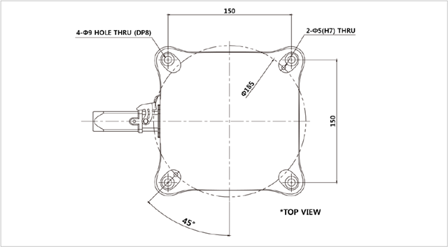
3.1 Fixating the robot base
Fixate the robot by fixing M8 bolts into the four 9.5 mm holes in the robot base.
- When fixing the bolts, it is recommended that you tighten them with a torque of 20 Nm.
- If you need to get the robot precisely installed in a fixed spot, you can do so by using a positioning pin of Φ5.
3.2 Placing the controller
When installing the control box onto a floor, allow 50 mm of clearance on both sides for ventilation in the control box.
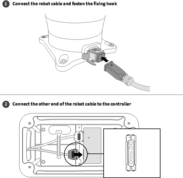
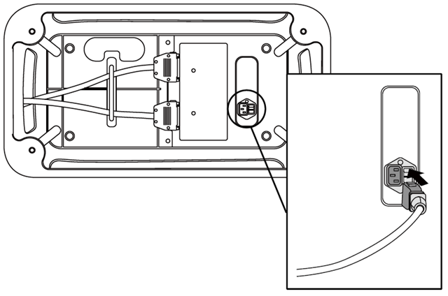
3.3 Connecting the robot to the control box
Connect the robot’s cable to the corresponding terminal of the control box and then secure the cable by fastening the fixing hook. Connect the other end of the robot cable to the corresponding terminal of the control box until it clicks, so that the cable does not come off.
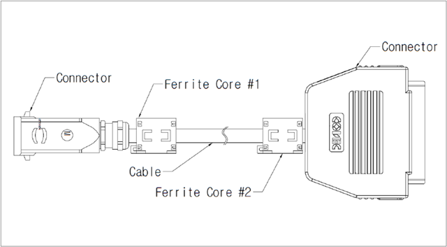
※ If the control box is affected by electromagnetic noise or, if it affects other equipment, ferrite cores should be installed for normal operation of the system. Ferrite cores need to be installed in the following locations.
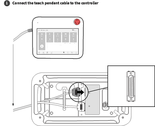
3.4 Connecting the control box to the teach pendant
Connect the teach pendant cable to the corresponding terminal of the control box until it clicks so that the cable does not come off.
- When you are using the teach pendant with it hung on a wall or the control box, be careful not to trip over its connecting cable.
※ If the teach pendant is affected by electromagnetic noise, or it affects other equipment, you must install ferrite cores for the normal operation of the system. Proper locations are described in the installation manual.
3.5 Plugging the robot into the control box
To plug the robot into the control box, connect its power cable to a standard IEC power plug.
- The cable must be connected to the standard power plug of the country.
- Make sure that the power plug is inserted all the way into the corresponding terminal of the control box so that it does not come off. You must connect the standard IEC C14 plug at the bottom of the control box with the corresponding IEC C13 cord.
- After connecting the robot’s power cable to the control box, make sure that the robot is properly grounded (electrical ground connection). Ground all pieces of equipment in the system by connecting them to a single common ground point with the unused screws among the screws associated with the grounding symbol in the control box. The ground conductor must have a current rating that is at least equivalent to the highest current in the system.
The electrical specifications of the control box are as follows. It must be connected to a power source that meets these specifications.
- Input voltage: 100 – 240 VAC
- Input power fuse (@100-240V): 15 A
- Input frequency: 47 – 63 Hz
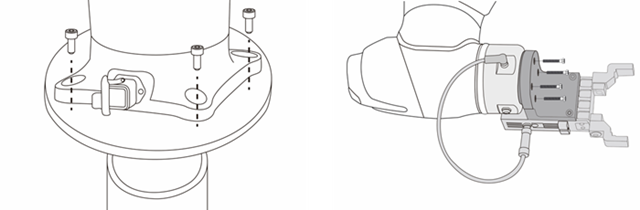
3.6 Connecting the robot and a tool
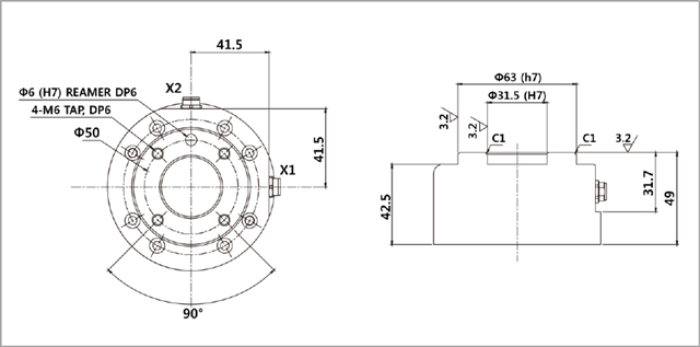
Use four M6 bolts to secure your desired tool to the tool flange.
- When fixing the bolts, it is recommended that you tighten them with a torque of 9 Nm.
- If you need to get the robot precisely installed in a fixed spot, you can do so by using a positioning pin of Φ6.
After securing the tool, connect the necessary cable to the tool’s I/O or Ethernet port.
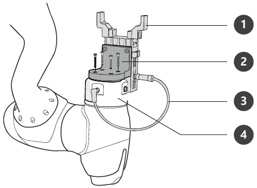
1. Tool, 2. Bracket, 3. Cable of the tool, 4. Tool flange
※ The mechanical specification of the tool flange – ISO 9409-1-50-4-M6.
4. Starting up the Robot
After the installation of the robot system, the user can start the robot by turning on the power.
4.1 Switching on the system power
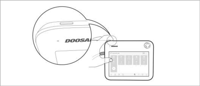
Press and hold down the power button in the upper left corner of the teach pendant.
- Then, the power to system essentials such as the robot, control box, and teach pendant is turned on.
- If you press the button again, the power is turned off.
※ If the system does not turn on, check the power switch located on the bottom of the control box.
When the robot is powered on, you can check the robot’s status through the LEDs in the robot and teach pendant. When the robot is initialized, the LED blinks red.
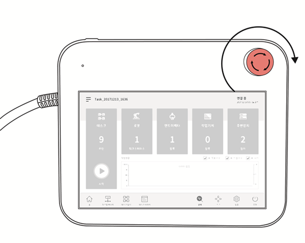
4.2 Releasing the emergency stop button
When the first boot is completed after the robot is installed, a warning popup will appear because the emergency stop button on the teach pendant is pressed. When this happens, the emergency stop button must be released to enable the robot.
- Turn the emergency stop button clockwise for release.
4.3 Disengaging packaging pose
The robot is in its packaging pose to allow easy transportation or packaging. To use the robot, the packaging pose must be disengaged.
- If the robot system needs to be packaged while using the robot, it can be changed to the packaging pose by using the packaging mode.
To disengage the packaging pose, follow the steps listed below:
1. Tap Status on the teach pendant.
2. Tap the Safety Recovery button.
3. Select the Packaging Mode tab.
4. Tap Servo On button.
5. The robot status display on the top right of the screen changes from Safety Off to Recovery. Tap the Packaging Mode toggle button on the Packaging Mode tab screen.
6. Tap the Disengage Packaging Pose button.
- The robot’s packaging mode is disengaged, and the robot moves to the home position. When the robot is in the home position, it does not move any further.
7. After the robot is in the home position, tap the ‘<’ Back button on the top left of the screen.
8. The robot status display on the bottom right of the screen changes from Recovery to Standby.
5. Configuring the Setting
The robot is now ready for use. In this section, you will learn how to set options such as language, date, and time, password according to the user’s environment.
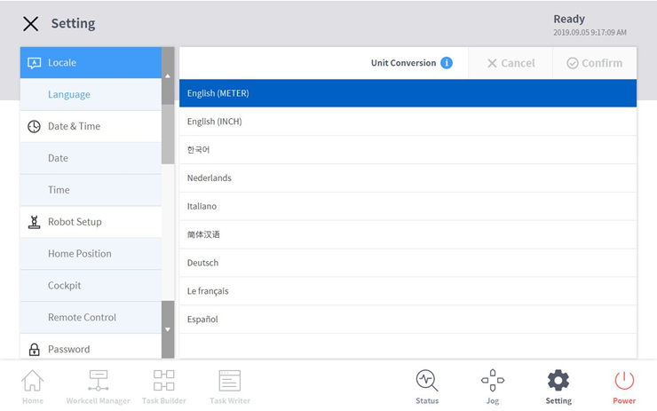
To configure environment settings related to the operation setting, tap the Settings button in the main menu.
5.1 Setting the language
In the Settings menu, select Language under Locale. Then, select your desired language from the language list and tap the Confirm button.
- Eight languages are supported: Chinese, English, French, German, Italian, Korean, Nederlands, and Spanish.
- To change the SI units to U.S. units, select “English (INCH)” and tap the “OK” button.
※ To apply the selected language, the system needs to be restarted.
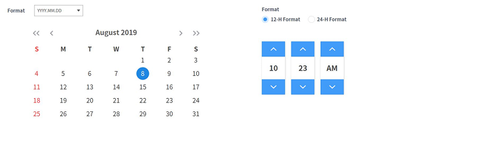
5.2 Setting the date and time
To set the date and time, tab the Settings button on the main menu and Select Date and Time. The specified date and time is used to record time-related variables such as the robot's usage (log) and program creation time.
- Even after changing the date and time of the system, the previously saved logs will be maintained in the original date/time before modification.
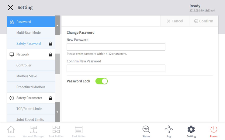
5.3 Changing and disabling the password
When accessing a setting menu with a lock mark, the user must enter a password. To change or disable the password option, tap Safety Password in Password menu.
- The default password can be found in the user manual.
- To disable the password lock, tap the Password Lock button.
- If the user forgets the set password, the robot system should be initialized as a factory reset.
6. Summary
In this course, how to install and get started with Doosan robot were introduced. Doosan robot provides the intuitive user interface and easy-to-use functions, but the user must know how to install and start the robot for safe and efficient use. In the settings menu, various options such as language, date and time, and password can be configured according to the user’s environment.
Please refer to the installation and user manual for more detailed instructions.
7. Recommended Resources
- Doosan Robotics Installation and User Manual, https://robotlab.doosanrobotics.com
※ Doosan Robotics has copyright and intellectual property rights to all content and all designs shown in this contents. Therefore, any use, copying, or dissemination of them without written permission from Doosan Robotics is prohibited. Please note that you will be held solely responsible for any improper use or alteration of the patent rights of Doosan Robotics.
Recommended Training Class
These learning opportunities can help you get started quickly.
Article
Programming with the robot’s PROFINET IO Device Function
Article
How to program with EtherNet/IP
Article
How to program using TCP/IP Socket