Log In
Training
Tutorial
Article
How to use Smart Setup (Automatic Measurement Function)
Basic
30 min
In this course, you will learn how to use the automatic measurement functions of Smart Setup.
1. Getting Started
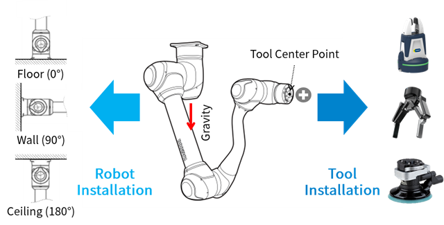
Doosan robot is equipped with Smart Setup that automatically measures installation mounting angles, weight of tools and location of their center points, allowing quick and easy robot installation and modification.
Based on the Joint Torque Sensor (JTS) installed in each axis, the control function provides the highest level of collision sensitivity in the industry, as well as the ability to measure self-installed mounting angles and tool weight.
The Tool Center Position (TCP) is automatically calculated with 4 location teachings to specify the tool coordinate system, which is essential to effectively manipulate the position of the tool mounted at the end of the robot.
In this course, you will learn how to use the Smart Setup provided by Doosan robot.
2. Automatic Robot Installation Pose Measurement
Doosan robot can be installed at any angle. Therefore, in order to use advanced control functions matched to the installed angle, such as direct control and force/compliance control, the robot installation angle must be entered accurately.
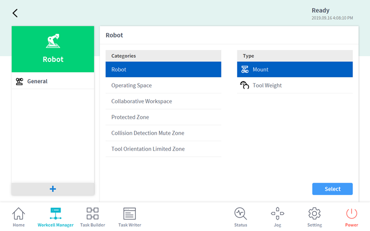
Select the robot installation pose from the robot category in Workcell Manager.
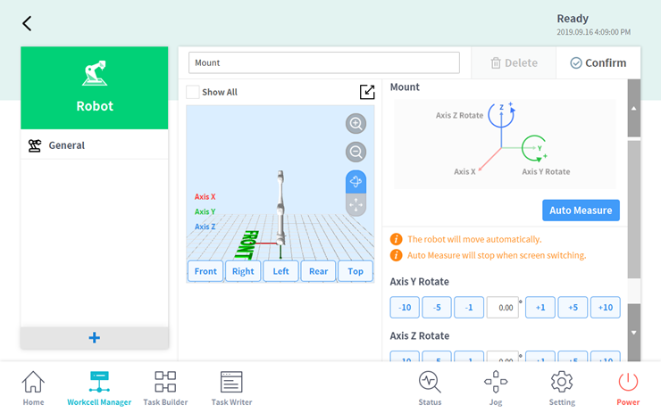
The auto-calculation button on the robot installation pose screen can automatically measure the robot installation angle. The measured angle is converted into the Y-axis and Z-axis and entered automatically.
- The user can directly enter the robot installation angle as well.
※ Precautions regarding automatic calculation are as follows:
- Remove any surrounding obstacles before performing automatic calculation.
- Be aware that the safety monitoring function is nullified during automatic calculation.
During automatic calculation, the auto-calculation button changes to the stop button. Press this button to stop.
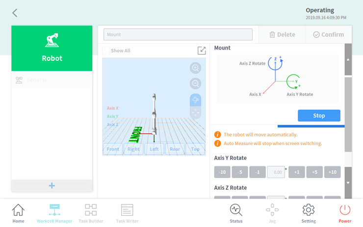
※ If the automatic measurement function is stopped and re-measured, the robot will operate from the initial starting pose, therefore pay attention to the safety of the user and robot.
[Try it]
Install the robot in a desired location and measure the installed angle with automatic measurement for robot installation pose.
3. Automatic Tool Weight/Center of Gravity Measurement
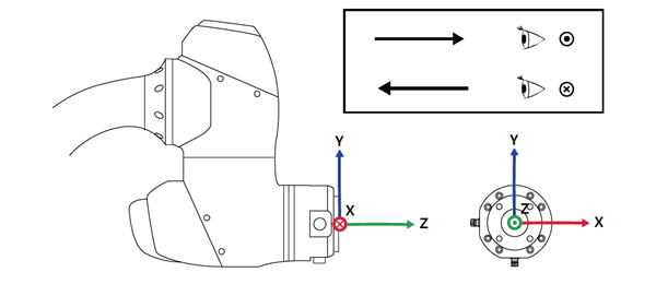
The weight/center of gravity for the tools used with the robot must be entered accurately in order to effectively use advanced control functions such as direct control and force/compliance control.
Refer to the figure below for the default TCP location for Doosan robot.
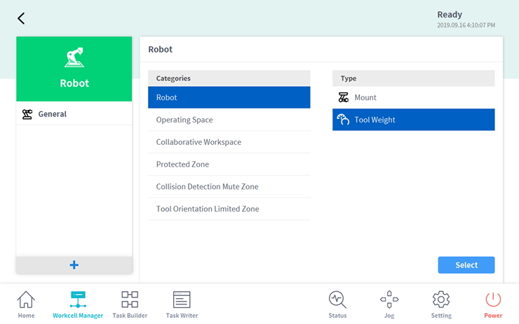
Doosan robot provides a tool weight measurement function to automatically measure the weight of tools mounted on the robot tool flange. Select tool weight from the robot category in Workcell Manager.
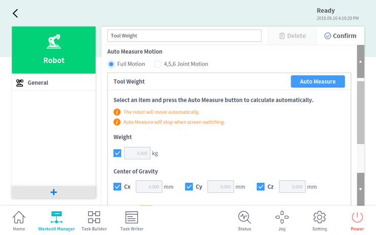
Tool weight can be measured easily with the auto-calculation button on the tool weight setting screen.
- Automatic motion calculation can be used with full operation using all six axes of the robot or partial operation using only axis 4, 5, and 6.
- Categories that can be automatically calculated are weight and center of gravity, and the user can select only the required category or both for automatic calculation.
※ Precautions regarding automatic calculation are as follows:
- Remove any surrounding obstacles before performing automatic calculation.
- Be aware that the safety monitoring function is nullified during automatic calculation.
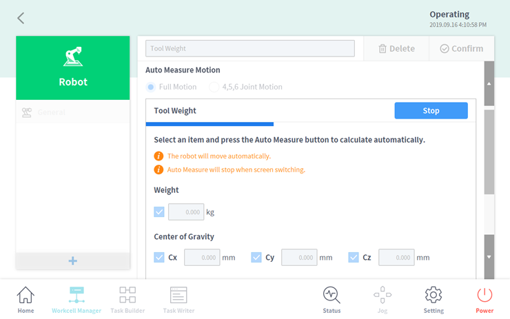
During automatic calculation, the auto-calculation button changes to the stop button. Press this button to stop, and in this case, the weight/center of gravity values will be initialized.
※ If the automatic measurement function is stopped and re-measured, the robot will operate from the initial starting pose, therefore pay attention to the safety of the user and robot.
[Try it]
Install the tool (gripper, power tools, etc) to use on the robot’s tool flange and measure the weight with automatic measurement for tool weight.
4. Automatic TCP Calculation
The TCP must be entered accurately to effectively manipulate the position of the tool mounted at the end of the robot. The TCP must be defined together with the position and rotation angle based on the flange coordinate system.
Select the Tool Center Position tab from the Workcell Item registered as an end effector in Workcell Manager.
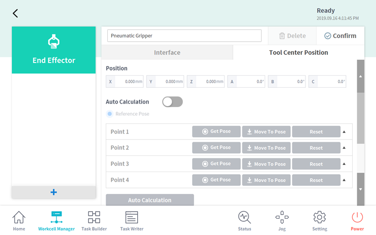
Tap the auto-calculation toggle switch.
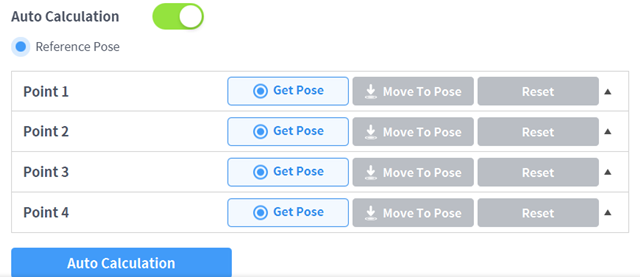
Then set the position to be the center point of the tool, set the reference position and enter the four positions using the Save Pose button to ensure that the center point of the tool remains constant. Refer to the figure below for instructions on entering the four positions.
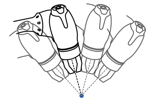
Detailed coordinate information about the position can be viewed each time it is saved.
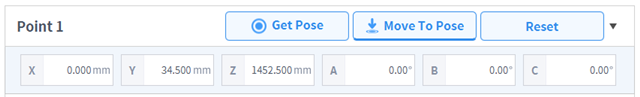
When the four positions are entered and the auto-calculation button is tapped, the values are updated in the position information area at the top.
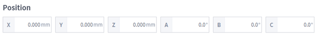
- If no values are entered for the four points and the auto-calculation button is tapped, all values are shown as 0.
- Automatic calculation is only for X, Y, Z positions, therefore the rotation angle must be entered by the user directly. The rotation angle can be entered with 3 categories: A, B, and C, which follows the Euler Z-Y-Z angle method. Please refer to the user manual for more detailed instructions.
[Try it]
Install the tool (gripper, power tools, etc) to use on the robot’s tool flange, calculate the TCP for that tool with the automatic TCP calculation function, and operate the tool through direct teaching or jogging on a TCP basis.
5. Summary
In this course, the Smart Setup automatic functions provided by Doosan robot that enable easy setup for robot installation pose, center of gravity, and tool center position, were introduced. The robot position or tool weight can also be directly measured on the field, but utilizing the Smart Setup will allow quick and easy configuration of the automation system. Please refer to the user manual for more details.
Recommended resources
- Doosan Robotics User Manual, https://robotlab.doosanrobotics.com
※ Copyright and intellectual property rights for all contents and design of this material are owned by Doosan Robotics. Therefore, any use, copying, or distribution without the written permission of Doosan Robotics is strictly prohibited. In addition, the user is solely responsible for the misuse or alteration of patent rights.
Recommended Training Class
These learning opportunities can help you get started quickly.
Article
Programming with the robot’s PROFINET IO Device Function
Article
How to program with EtherNet/IP
Article
How to program using TCP/IP Socket